The 'Functions and variables area'
The 'Functions and variables area' (for the different areas on the Property Calculator form, see The Property Calculator) contains the following three sections:
- Properties and Variables - Here you find variables, mathematical constants and properties that are existing for (or directly related to) the selected 'Target Object'.
- Functions - Here you find all built-in functions to generate default expressions based on existing properties in your solution. The functions are grouped in several categories. Not all functions are available for all object types.
- Operators - An 'operator keypad' for convenience when generating expressions.
For an overview of all the functions, variables and mathematical constants, see Property Calculator functions and examples.
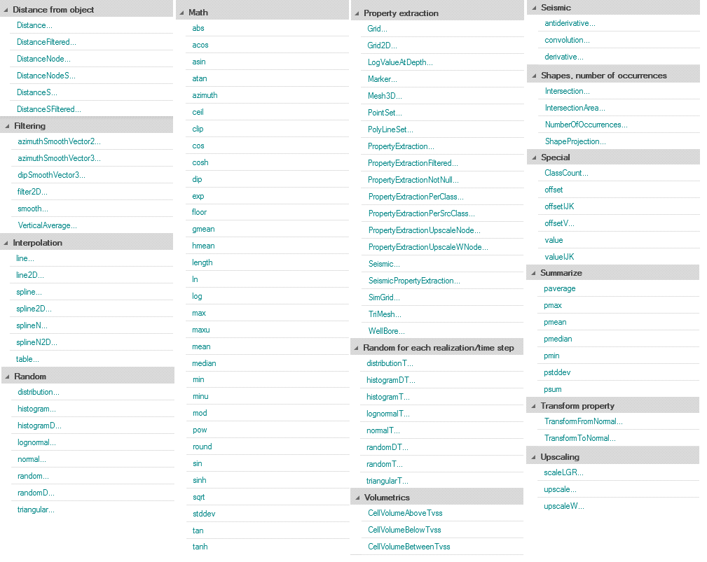
Functions (per category) under the Functions section on the Property Calculator form. Note that the list of functions is interactive, which means that different functions can be available, depending on the selected 'Target object' (e.g. 3D grid, tri-mesh, seismic.segy, wellbore, etc.). click to enlarge
Function parameters
When you activate a function, you will in many cases automatically be asked to supply input for relevant parameters.
In some parameter windows you can enter a default value. This is the value given to undefined data points in the calculator result.
Example 1
3D grid and Filtering/Smooth click to enlarge
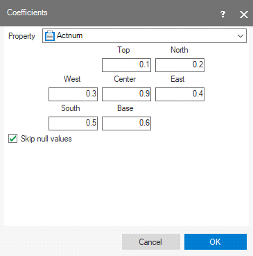
In this example, the a 3D grid is the 'Target object' and the function is 'Smooth' (function category 'Filtering').
The 'Smooth' function calculates a ‘new’ property value for each grid cell as an average of the cell’s value and the weighted values of its surrounding cells. The function asks you to select the property that must be smoothed and to specify a ‘weight’ for the neighboring cells. The weight defines the extent to which the neighboring grid cell’s property values contribute to the calculation.
The higher the weight, the greater the contribution.
The new, smoothed property value in the above example is calculated as
(0.1*Top cell value + 0.2*North cell value + 0.3*West cell value + 0.9*Center cell value + 0.4*East cell value + 0.5*South cell value + 0.6*Base cell value) / (0.1 + 0.2 + 0.3 + 0.9 + 0.4 + 0.5 + 0.6)
The settings shown result in the following calculator expression:
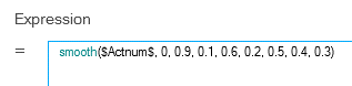
Example 2
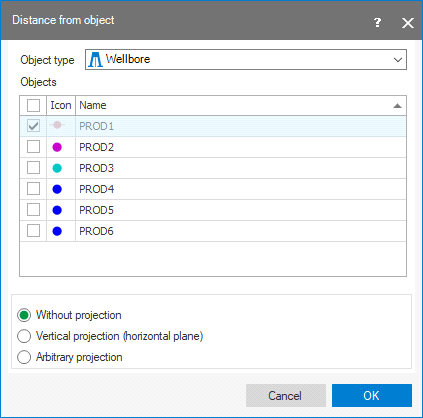
3D Grid and Distance from object (function 'Distance') click to enlarge
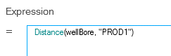
In this example, the 3D Grid is the 'Target object' and the function is 'Distance' (function category 'Distance from object'). This function calculates the distance of all grid cells to another object. In the shown example, the object is wellbore PROD 1. Note that in order to select a wellbore, the Object type must be set to 'Wellbore'. Also, you have to set the Projection (see below).
The settings shown result in the following calculator expression:
Projection
For several functions the Property Calculator can compute absolute values or projected values, for others it must use projected values. Projected values mean that both the source (in the above example the wellbore PROD 1) and the target (in the above example the grid cells) are projected on a plane with a user-defined orientation in space. For instance distance is then calculated as the distance between source object and target object on this projection plane.
The projection plane is defined in the parameter pop-up window that appears after activating the function. See the ‘Distance from object’ image above.
There are three options:
Without projection No projection applied. Absolute values are calculated.
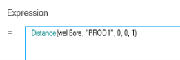
Vertical projection (horizontal plane) Source and target are projected on a horizontal plane. Values are calculated based on the projected positions. The vertical direction (0,0,1) will appear in the expression. Resulting expression (in above Distance example):
Arbitrary projection Source and target are projected on a plane with arbitrary orientation in space. Values are calculated based on the projected positions.
When the option ‘Arbitrary projection’ is selected, you are asked to define the projection plane as follows:
Enter a relative axis length in the Northing, Easting and Depth direction.
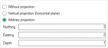
These three relative lengths define the orientation of a vector in 3D space. This vector is the normal on the projection plane.
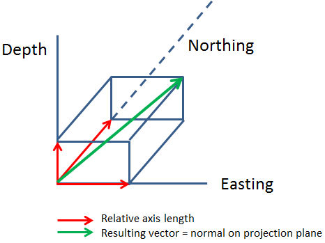
click to enlarge
In the calculator expression, the orientation of a projection plane is indicated by a set of three numbers, which represent the relative N, E and Depth axis lengths that define the normal on the projection plane.
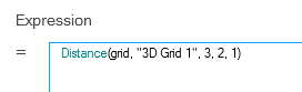
Remember that it is the relative axis length that counts, so, again in this example, the values 3,2,1 lead to the same result as would values 6,4,2, or 9,6,3, etc.